Gimbal electronics
Complete electronics for a three-axis gimbal. A mainboard, three round BLDC motor drivers with magnetic encoders and an IMU board, all connected over RS-485. Designed and assembled by me.
The system consists of five boards: a mainboard, three identical motor drivers and an IMU. Each board has its own STM32, and they talk to each other over full-duplex RS-485. The Molex Pico-SPOX connectors carry both the bus and the supply to every board.
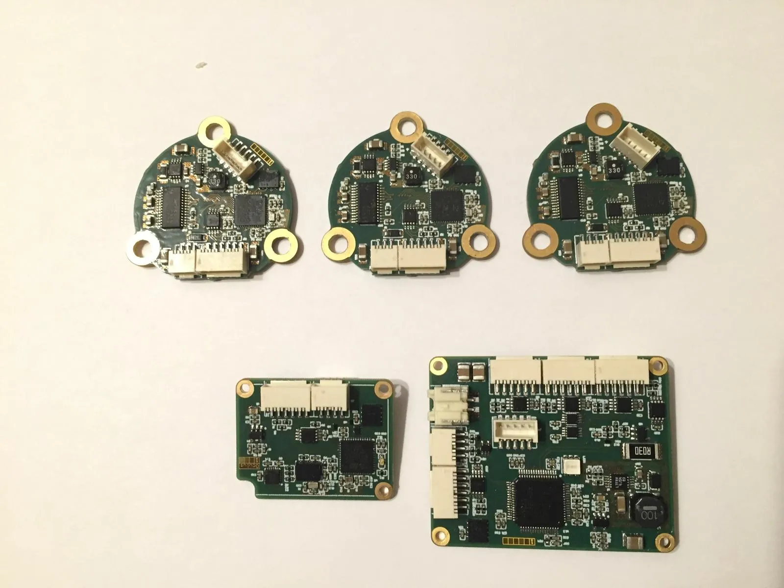 The complete set: three motor drivers, with the IMU (left) and the mainboard (right) below.
BLDC motor driver
The round drivers sit directly on the motor. The AS5047D magnetic encoder measures the rotor position, the DRV8313 drives the three phases, and the motor current is measured across a shunt.
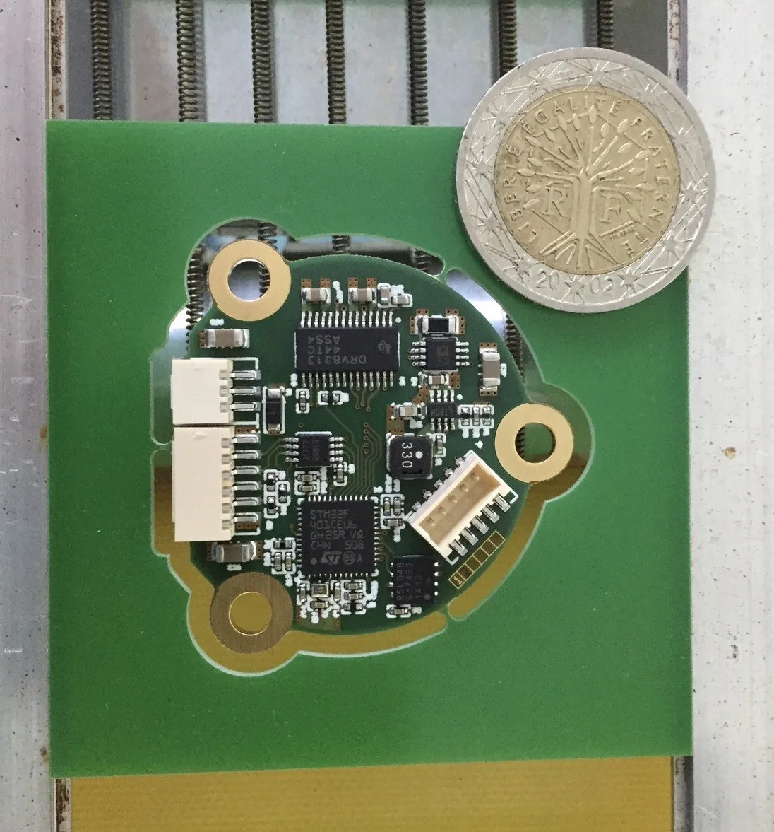 Freshly assembled and still in the panel. The 2-euro coin shows the scale.
| Function | Part |
|---|---|
| Microcontroller | STM32F401CCU6 |
| Motor driver | DRV8313, three integrated half-bridges |
| Rotor position | AS5047D, magnetic encoder over SPI |
| Current sensing | AD8418 across a 50 mΩ shunt |
| Supply | LT3470, buck from motor voltage down to 3.3 V |
| Bus | ISL3177, full-duplex RS-485 |
| Memory | FM25CL64B, 64 Kbit FRAM |
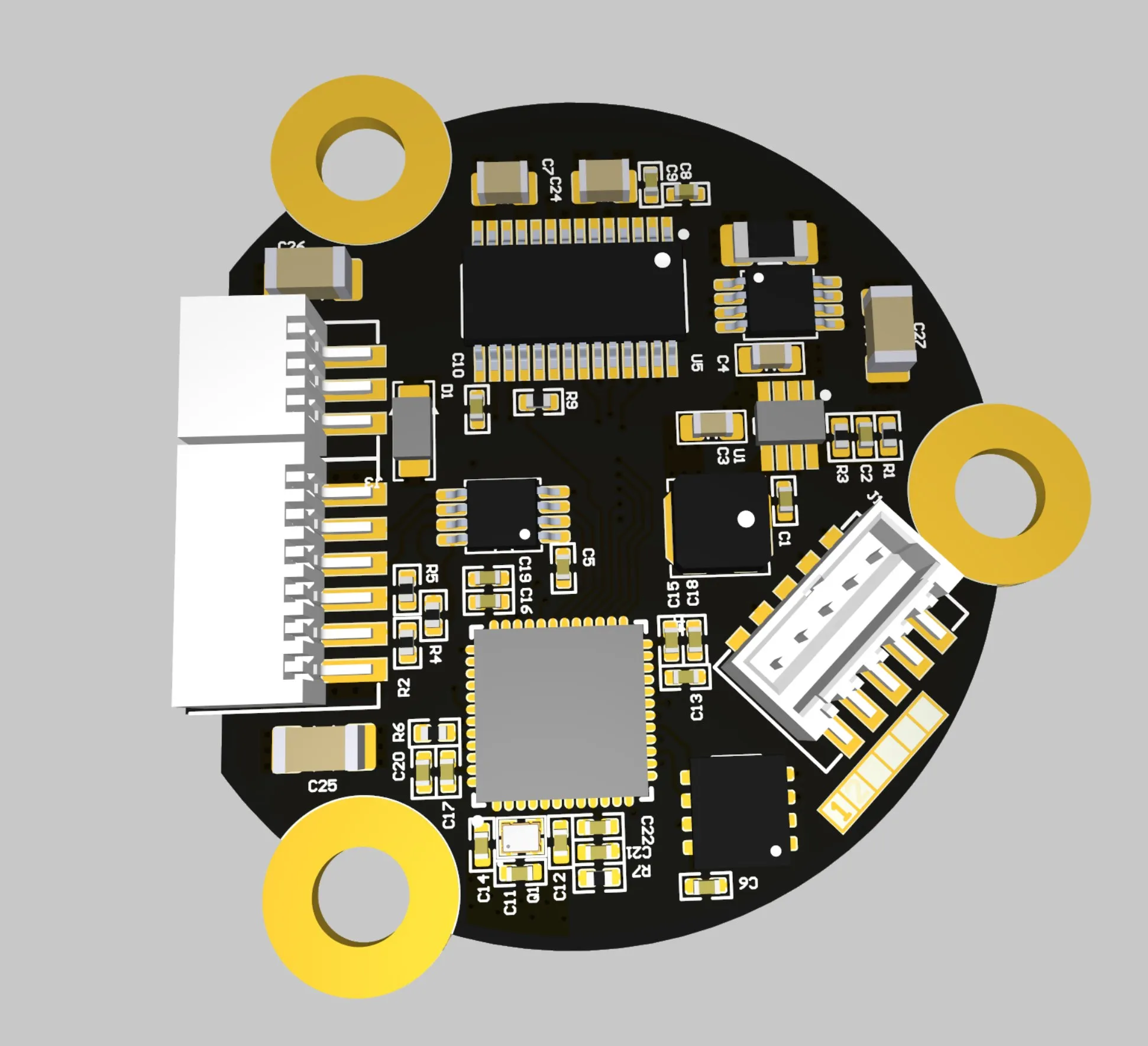
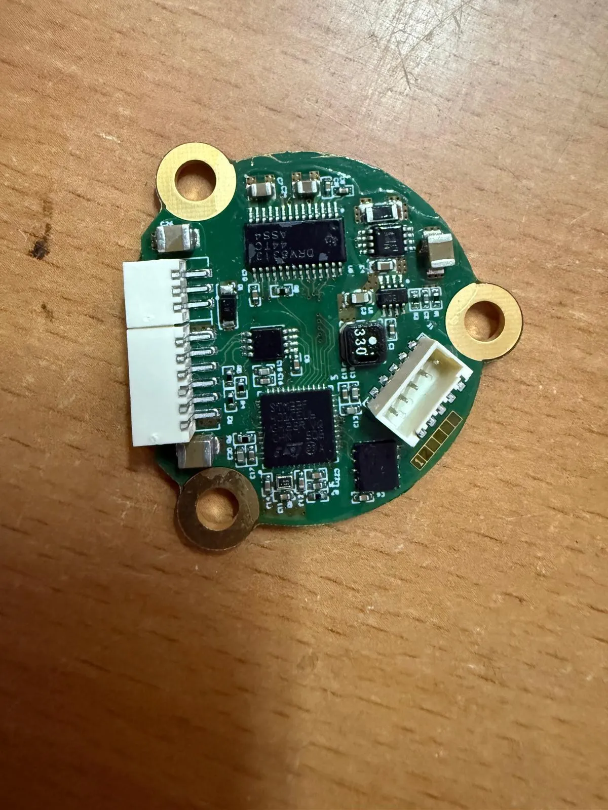 The layout in 3D view and the finished board.
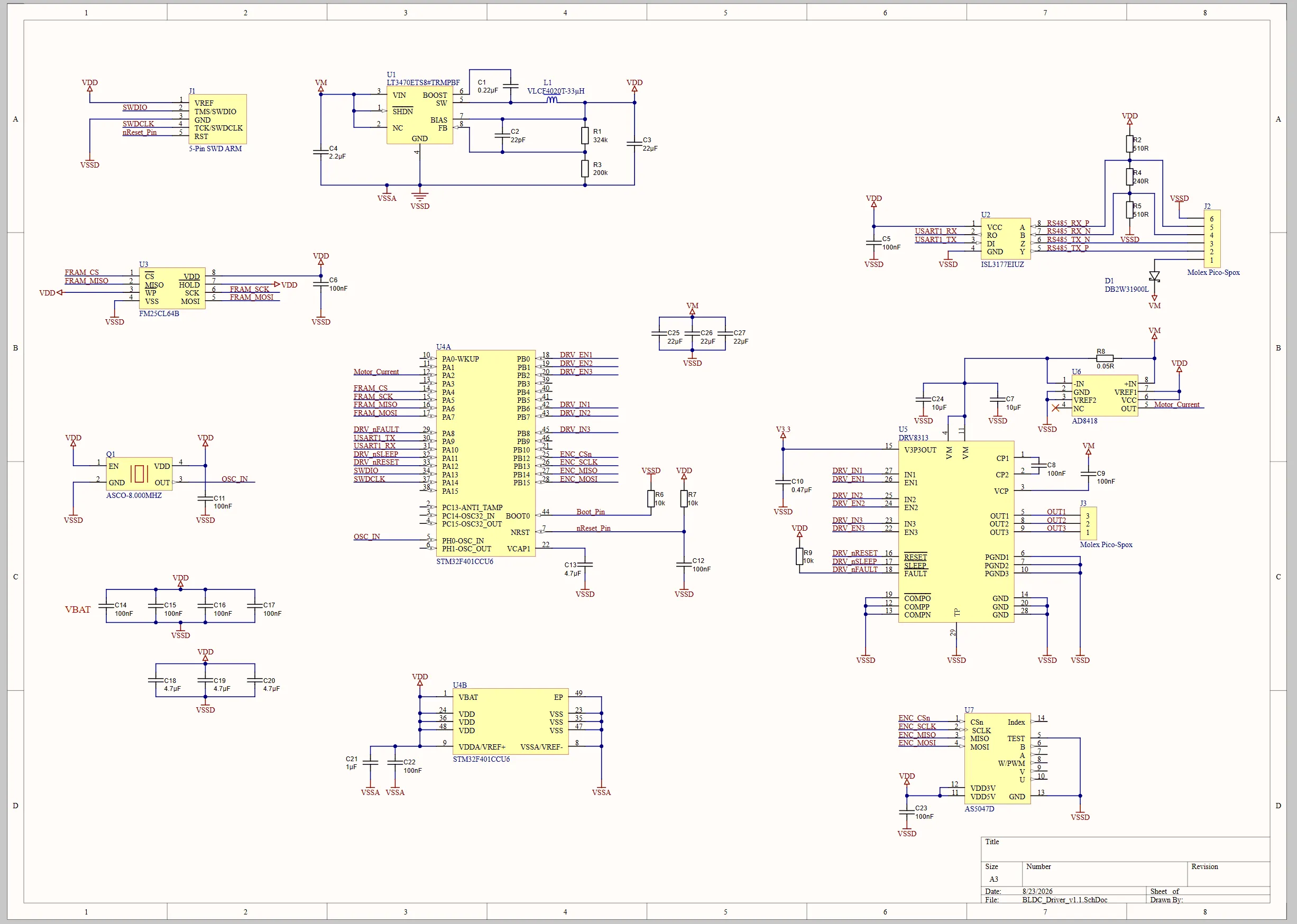 Schematic of the driver. Click to enlarge.
IMU board “Oculus”
The IMU measures the orientation of the gimbal. It carries two sensors: an MPU6500 on SPI and a BNO055 with on-chip sensor fusion on I²C. It can also output an SBUS signal whose polarity can be switched through an XOR gate.
| Function | Part |
|---|---|
| Microcontroller | STM32F401CEU6 |
| Sensors | MPU6500 (SPI), BNO055 (I²C) |
| Supply | LP2985, LDO to 3.3 V |
| Bus | ISL3177, full-duplex RS-485 |
| SBUS output | SN74LVC1G86 as a switchable inverter |
| Memory | FM25CL64B, 64 Kbit FRAM |
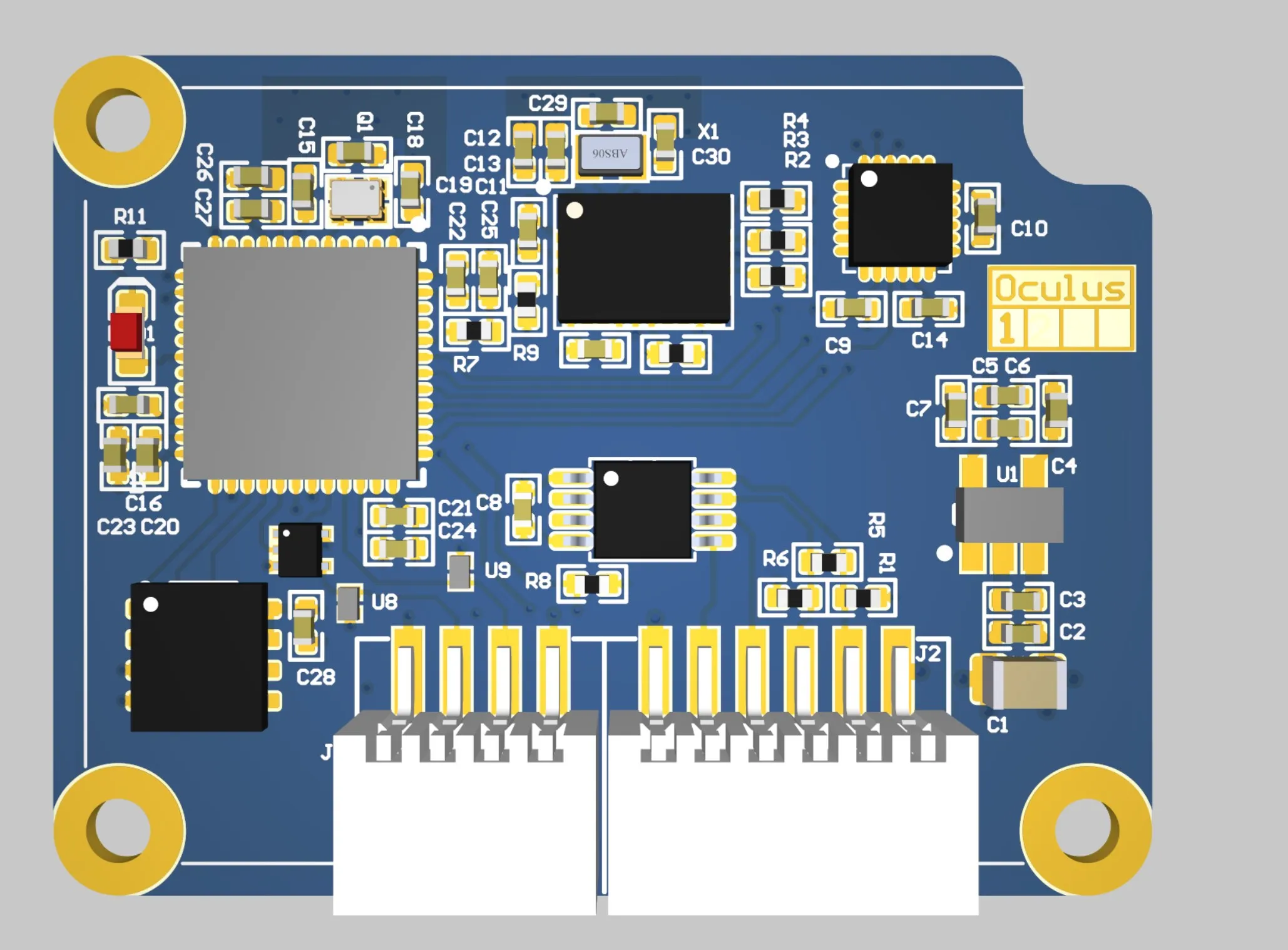
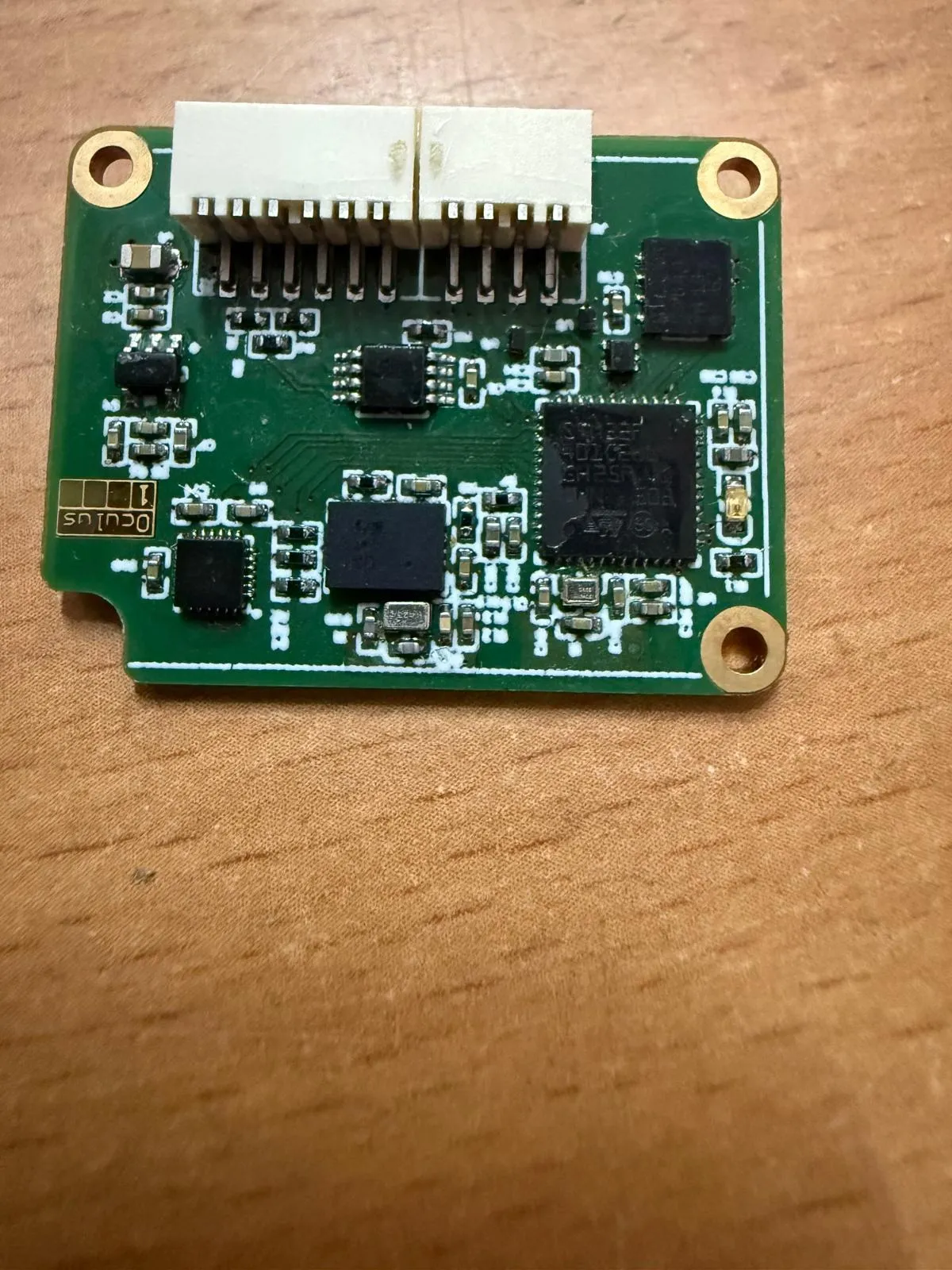 Layout and assembled board.
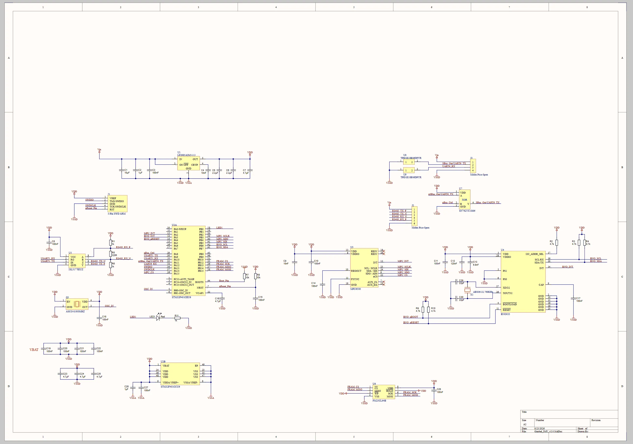 Schematic of the IMU, revision 2.0. Click to enlarge.
Mainboard
The mainboard is the hub. It has five RS-485 ports for the drivers, the IMU and a system connector, an SBUS input for the radio receiver, and it measures input current and voltage. Analog switches select which of the controller’s UARTs goes to which port.
| Function | Part |
|---|---|
| Microcontroller | STM32F405RGT6 |
| Supply | LT3991, buck to 5 V, followed by an LP2985 to 3.3 V |
| Bus | 5 × ISL3177, full-duplex RS-485 |
| UART routing | 2 × TS5A3359, 1-of-3 analog switches |
| Measurement | AD8211 across a 30 mΩ shunt, divider for the input voltage |
| Radio | SBUS input with an SN74LVC1G86 as inverter |
| Memory | FM25CL64B, 64 Kbit FRAM |
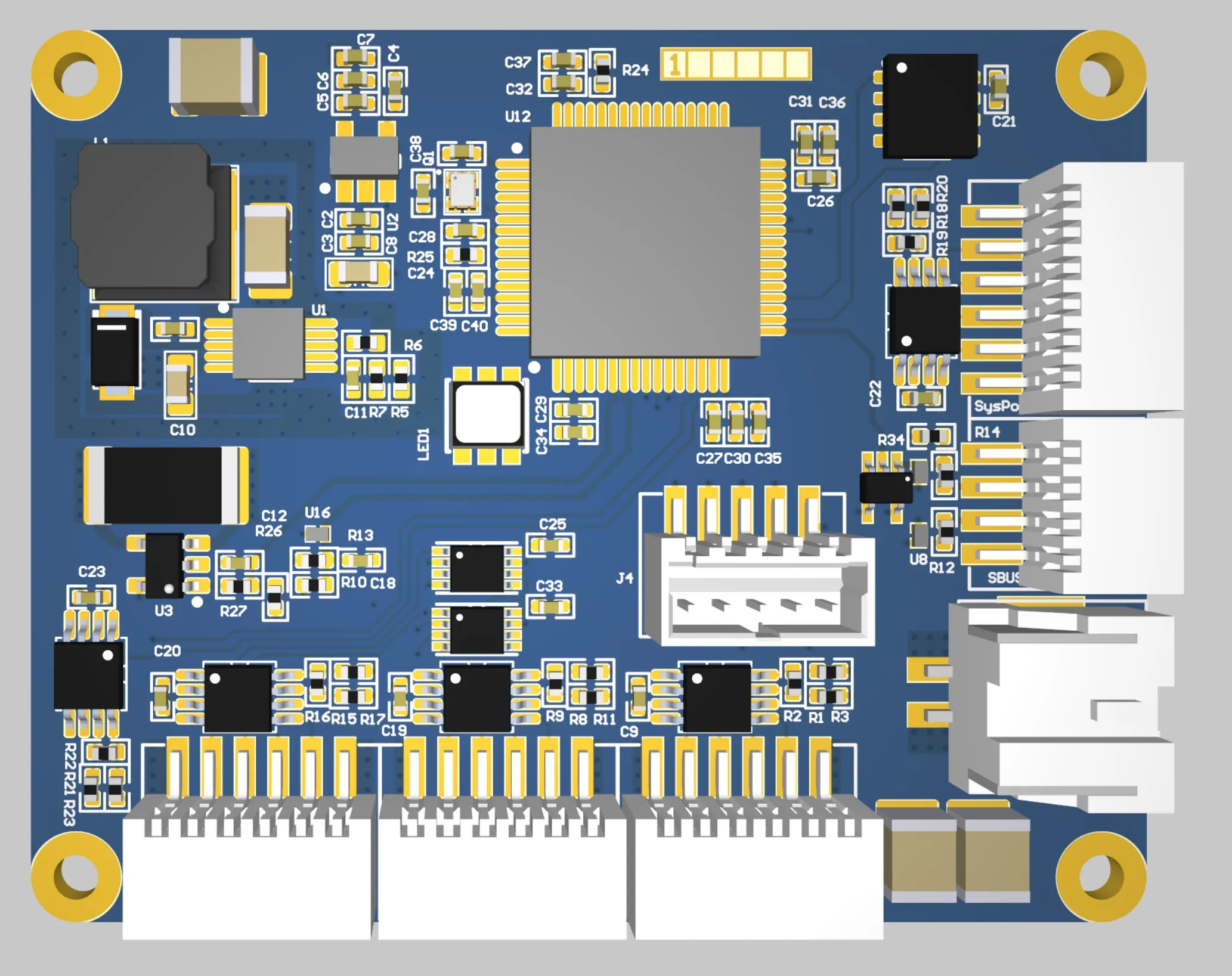
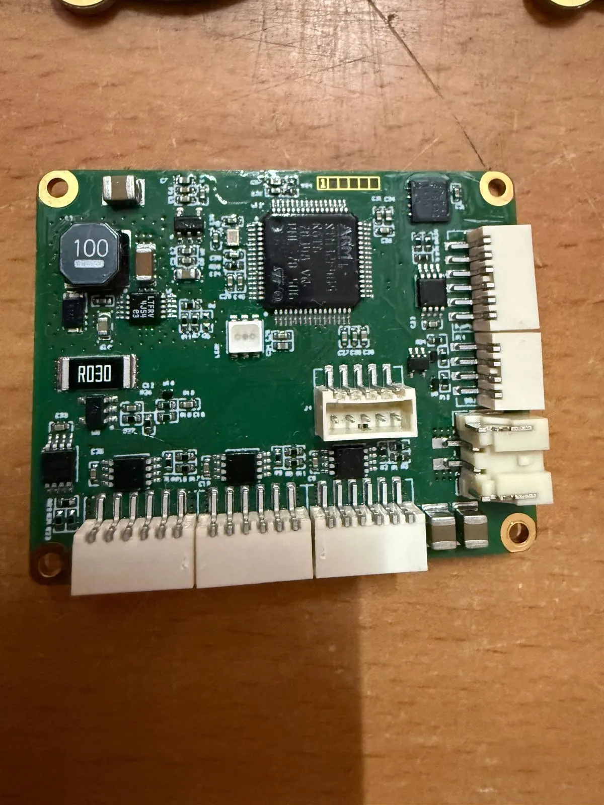 Layout and assembled board.
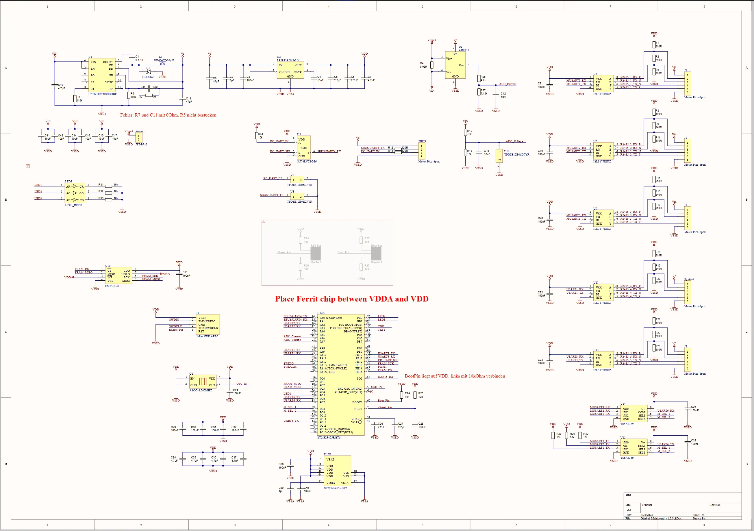 Schematic of the mainboard. Click to enlarge.
From the bring-up
The red notes in the schematics are fixes from the first bring-up. On the mainboard these include a BOOT0 pin that was tied directly to VDD and had to be connected through a 10 kΩ resistor instead, a change to the LT3991 compensation network, and an additional ferrite between VDDA and VDD.